RJ-45 Plug Body, Jack Housing and Contact Design Issues
Non-Compliant Product Designs Are Affecting Signal Quality
Resulting in Poor Signal Transmission, Intermittencies, Shorts and Potential Signal Loss
CAVEAT EMPTOR.....Let The Buyer Beware
THERE IS A DISTURBING TREND OF MODULAR PLUGS AND JACKS NOT MEETING SPECIFICATIONS PUT FORTH BY THE TIA, UL, IEC AND FCC CAUSING SIGNAL INTEGRITY ISSUES
THE NEWEST PROBLEM
RJ45s Made with 94V-2 Material
Violates UL Standard That Calls Out 94V-0 Material
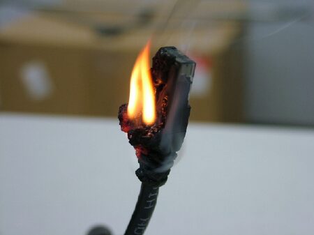
UL STANDARDS call out a polycarbonate material meeting UL FLAME AUTO EXTINGUISH.....94V-0 rated. This material will self extinguish during the prescribed time allowed by UL. Some manufacturers are offering 94V-2 material.....why.....because it is a cheaper compound....problem is.....IT BURNS AND PROMOTES THE SPREAD OF FIRE. That means in a high density application, such as a Data Center with tons of Patch Cables.....you have a really nice FUEL SOURCE!
Additional Problems
CONTACT "LIFT OFF"
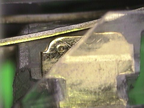
THE PLUG CONTACT (BLADE) IS NOT MAKING ANY CONTACT WITH THE JACK WIRE (CONTACT)
This is occurring more and more frequently and is caused by the JACK BEING TOO WIDE (on Ethernet Servers, Switches, Routers, etc. and Wall Outlets) and NOT CONFORMING TO THE DIMENSIONS SPECIFIED BY THE STANDARDS BODIES.
In addition, specifications clearly define critical RJ45 JACK DIMENSIONS with TOLERANCES and MOLD DRAFT REQUIREMENTS to INSURE PROPER LATCHING, PLUG/JACK TARGETING and GUIDANCE and.....APPROPRIATE SURFACE AREA CONTACT MATING for signal transmission integrity. This is like opening up a can of worms.....and there HAVE BEEN DOCUMENTED AND PROVEN RJ45 FIELD CONNECTIVITY FAILURES. Again, the problems are the result of POOR MOLD DESIGN, WORN OUT TOOLING, POOR QUALITY CONTROL PROCEDURES, SHRINKAGE CHARACTERISTICS, PLASTICS USED, etc.
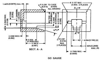
JACK HOUSING DESIGN MIN and MAX DIMENSIONS
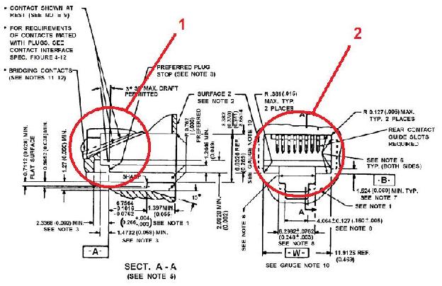
Here are a few examples taken from the above drawing that may impact CONTACT LIFT OFF.....
1) PLUG/JACK LATCHING - One of the most critical dimensions is the plug tab and latching mechanism combined with the jack latching stop. You would like to hear a "CLICK" after mating. Unfortunately, some manufacturers have "CUT CORNERS" (literally) and have breached the MOLD DRAFT DESIGN specification. Part design includes DRAFT FEATURES (angled surfaces) to facilitate removal from the mold.....by ignoring the prescribed mold draft, manufacturers can spit our more products faster, since dimensional tolerance specifications govern the part cost and manufacturability. An improper draft for this critical occurrence can actually lift the plug angle slightly, enough to cause intermittent contact or loss of signal.
2) HEIGHT and WIDTH OF JACK OPENING - Specifications clearly define the MINIMUM and MAXIMUM RJ45 JACK OPENING DIMENSIONS/TOLERANCES to insure PROPER TARGETING and GUIDANCE of the plug into the jack. We have observed that some suppliers are not in compliance with these dimensions....the end result, POOR MATING CHARACTERISTICS WITH THE RJ45 JACK (WIGGLE, DROOP or RISE) causing INTERMITTENCIES or SIGNAL LOSS.
PLUG BODY DESIGN MIN and MAX DIMENSIONS
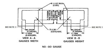
MAXIMUM PLUG SIZE
MAXIMUM PLUG SIZE
Specifications clearly define the MINIMUM and MAXIMUM RJ45 PLUG SIZE DIMENSIONS to insure PROPER TARGETING and GUIDANCE into the RJ45 Jack. We have observed that some suppliers are not in compliance with these dimensions....the end result, POOR MATING CHARACTERISTICS WITH THE RJ45 JACK (WIGGLE, DROOP or RISE) causing INTERMITTENCIES or SIGNAL LOSS. In another case, the PLUG WOULD NOT FIT INTO THE JACK OPENING. The problems are indicative of POOR MOLD DESIGN, WORN OUT TOOLING, POOR QUALITY CONTROL PROCEDURES, SHRINKAGE CHARACTERISTICS, PLASTICS USED, etc.
SELECTION OF CONTACT BASE METAL PHOSPHOR BRONZE versus BRASS CONTACTS
Selection of the BASIS METAL for the CONTACTS will have a SIGNIFICANT EFFECT ON THE PERFORMANCE CHARACTERISTICS or THE PLUGS and JACKS. This is due to the granular MICROSTRUCTURE of the metal and its impact on STIFFNESS, SPRING QUALITY, CORROSION and WEAR RESISTANCE. Why do some manufacturers use brass instead of phosphor bronze....because it's cheaper....and so is its POROSITY, SOFTNESS and MECHANICAL CHARACTERISTICS.
PLUG CONTACT DESIGN THE SOLID versus STRANDED CONDUCTOR ISSUE
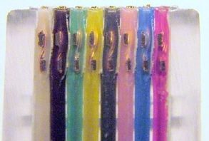
Some manufacturers promote two (2) different contact designs....one for SOLID CONDUCTOR and the other for STRANDED CONDUCTOR....why not use ONE PLUG THAT ACCOMMODATES BOTH TYPES OF CONDUCTORS.....SENTINEL'S DOES. This contact design is meant to "STRADDLE" the conductor, instead of "PIERCING" the conductor straight down (this could fracture solid conductors). See FLUORESCENT X-RAY below of the contacts straddling the conductors.
PLUG BODY and CONTACT DESIGNCONTACTS (BLADES) FALLING OUT OF PLUG BODY
Some manufacturers contacts (blades) in the RJ45 PLUGS ARE FALLING OUT!!!!! This is a result of.....poor plug body and/or contact design....cheap tooling.....bad tolerances.....poor staking equipment (to set the blades into the plug).....the wrong plastic compound for the plug body (too soft or too hard).....and a host of other reasons.
The RJ-45 Is A Highly Engineered Interconnection System
CAVEAT EMPTOR.....Let The Buyer Beware
SUB-STANDARD, NON-COMPLIANT and COUNTERFEIT RJ45's coming in from the Far East
KNOW THE STANDARDS - KNOW THE SPECS - INSIST ON COMPLIANCE - KNOW YOUR SUPPLIERS
