RJ-45 Plug/Jack Surface Contact Mating Problems
Proven RJ-45 Interconnect Problems Are Affecting Signal Quality
Resulting in Poor Signal Transmission, Intermittencies, Shorts and Potential Signal Loss
The RJ-45 Is A Highly Engineered Interconnection System
CAVEAT EMPTOR.....Let The Buyer Beware
SUB-STANDARD, NON-COMPLIANT and COUNTERFEIT RJ45's coming in from the Far East
KNOW THE STANDARDS - KNOW THE SPECS - INSIST ON COMPLIANCE - KNOW YOUR SUPPLIERS
The Following Excerpts are Taken from FCC Regulations and TIA Specifications
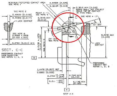
1. "The plug/jack contact interface should be hard gold to hard gold and should have a minimum gold thickness of .0012700 mm (0.000050 inch) on each side of the interface. The minimum contact force should be .98 N (100 grams). Any non-gold contact material must be compatible with gold and provide equivalent contact performance. A smooth, burr-free surface is required at the interface in the area shown."
2. "The jack contact design is based upon .4572mm (.018 inch) spring temper phosphor bronze round wire in the modular plug blade and jack contact surface. Other contact configurations that provide contact performance equal to or better than the preferred configurations and do not cause damage to the plug or jack are permitted. The preferred jack contact width is .44958/.49530 mm (.0177/.0195 inches). Deviations from the preferred jack contact
width are permitted for round contacts as well as non-circular cross sectional shapes but they must be compatible with existing plug configurations. The requirements of Note 1 apply to all possible contact areas.
3. The configuration of the plug contact and the front plastic of the plug should prevent jack contacts from being damaged during plug insertion into jacks.
4. This is the suggested nominal contact angle between plugs and jacks with the plug latched into the jack. If this angle becomes greater than 24 degrees loss of electrical contact may occur between the plug and jack. If the nominal contact angle becomes less than 13 degrees, interference between jack contacts and the internal plastic in the plug may occur.
HERE IS WHAT WE ARE SEEING
NON-COMPLIANCE - CHEATING - COST CUTTING OPERATIONS AFFECTING PRODUCT QUALITY
What you should be aware of when selecting your supplier/partner.
PLUG/JACK CONTACT SURFACE MATING AREAS
PLUG/JACK MATING AREA SPECS MIN and MAX DIMENSIONS
Specifications clearly define critical RJ45 PLUG/JACK TARGETING and GUIDANCE, BURR FREE CONTACT SURFACES and APPROPRIATE SURFACE AREA CONTACT MATING for signal transmission integrity. This is like opening up another can of worms. Again, the problems are the result of POOR MOLD DESIGN, WORN OUT TOOLING, POOR QUALITY CONTROL PROCEDURES, SHRINKAGE CHARACTERISTICS, PLASTICS USED, etc. Here are a few examples of situation you may encounter causing.....
PREMATURE CONTACT WEAR
HARMONIC PHENOMENON IN DATA CENTERS
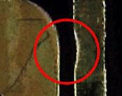
If proper design elements and tolerances are not followed....or specifications not adhered to......there is a strong possibility for Premature Contact Wear. If Minimum Nominal Forces between the contacts are not made, there can be friction due to vibration, thermal cycling of a host of other reasons that can cause undue contact wear. If you combine this, with using inferior, out of spec materials, incorrect plating materials and thicknesses....undue wear becomes a big problem, especially in Data Centers. This is known as the HARMONIC PHENOMENON IN DATA CENTERS where the environment induces harmonics leading to slight vibrations that wear off the gold plating on the contacts.
PROPER PLUG BLADE DEPTH TERMINATED CONTACTS (BLADES) HAVE A MIN/MAX DEPTH SETTING
The specifications clearly define the MINIMUM and MAXIMUM CONTACT BLADE SETTING DEPTH and THE MINIMUM SURFACE TO SURFACE CONTACT MATING AREA DIMENSIONS. In one example, the BLADES WERE SET SO DEEPLY THAT THERE WAS NO CONTACT BETWEEN THE PLUG AND JACK.
"WIGGLE TEST" PLUG/JACK CONTACT SURFACE MATING AREAS
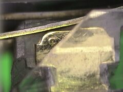
One of the most frequent tests performed by OEM's is the "WIGGLE TEST".....sometimes also referred to as the "GORILLA TEST". Simply stated, the test consists of INSERTING THE PLUG INTO THE JACK AND "WIGGLING" IT.....BACK AND FORTH.....RIGHT TO LEFT.....SEVERAL TIMES. If proper specifications are not adhered to, the PLUG PLASTIC WILL CAUSE THE JACK CONTACTS TO "RIDE UP" or "LIFT OFF" the PLUG CONTACT.
This content requires the Adobe Flash Player. Get Flash
BEND RADIUS EFFECTS ON SIGNAL INTEGRITY DROOP EFFECT AND RISE EFFECT
When the PLUG (i.e cable assembly) is inserted into the JACK, it should lead STRAIGHT INTO THE JACK to insure PROPER TARGETING, GUIDANCE and MAXIMUM SURFACE MATING AREA CONTACT to maintain signal integrity. Shown below, the cables on the bottom of the patch panel show possible DROOP EFFECTS, while the cables on the top of the patch panel show potential RISE EFFECTS. There may be interconnection issues where the ANGLE CREATED by the DROOP or RISE will DECREASE THE SURFACE CONTACT MATING AREAS affecting signal Integrity.

NOTE: As cable constructions are getting bigger and bigger.....and heavier and heavier.....this problem is occurring more and more often.
BEND RADIUS EFFECTS ON SIGNAL INTEGRITYHORIZONTAL ANGLE DEFLECTION CAUSING LIFT OFF
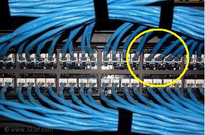
Highlighted in the yellow circled area, are cables that may be affecting signal integrity be the ANGLE OF DEFLECTION caused by the BEND RADIUS OF THE CABLE ASSEMBLY INTO THE JACK. If severe enough, you will have "LIFT OFF", whereby, the PLUG PLASTIC LIFTS THE JACK CONTACT UP and you lose your signal.
BEND RADIUS EFFECTS ON SIGNAL INTEGRITYHORIZONTAL ANGLE DEFLECTION CAUSING LIFT OFF


Sentinel Connector Systems is the premier "MADE IN USA" manufacturer of RJ-45 Plugs and Jacks. As a matter of fact, their Founder was part of the original design team at Hardesty that actually built the first RJ type connector ever. We have the BOOK OF RJ.....representing over 40 years of hand written notes about the why's and dont's of manufacturing RJ-45 Interconnection Systems.
THE BOOK OF RJ (Robert J Brennan)

WE DO EVERYTHING FOR A REASON
The guys at Sentinel have OVER 300 MAN YEARS OF EXPERIENCE, HOLD 35 RJ45 RELATED PATENTS and HAVE THE ANSWERS to all of your RJ-45 related questions. We are just a phone call or email away.
THE SENTINEL CONNECTOR SYSTEMS ADVANTAGE - All of Sentinel's Plugs and Jacks are built in accordance to INDUSTRY STANDARDS & SPECIFICATIONS as set forth by governing bodies such as ACTA, ASTM, EIA, FCC, IEC, IEEE, ISO, TIA and UL. Sentinel is also a Member of the Communications Cable and Connectivity Association.....adhering to the Association's STRICT CODE OF ETHICS regarding compliance.
OUR PRODUCT DESIGN ELEMENTS - The BASIS METAL for the contacts is PHOSPHOR BRONZE. We use a very specific % along with a very tightly controlled min-max granular MICROSTRUCTURE to provide the best STIFFNESS, SPRING QUALITIES and CORROSION & WEAR RESISTANCE. The base metal is then ELECTROPOLISHED (versus wire brushed) creating an extremely smooth "BURR FREE" CONTACT SURFACE. It is then plated with 100 micro inches of pure Nickel (min plugs, 50 micro min jacks)....providing a sacrificial metal surface/barrier to PROHIBIT DIFFUSION and OBTAIN DESIRED POROSITY CHARACTERISTICS....then 50 micro inches (minimum) of pure 24 CARAT (hard) GOLD adhering to MIL-G-45204C, TYPE II, GRADE A specifications and Knoop Hardness requirements. During each plating operation, PROPER SURFACE ACTIVATION and CLEANSING PROCEDURES are meticulously followed to insure against any possible surface contamination and potential GALVANIC REACTIONS (reference MIL-STD-889).
By incorporating the strict design guidelines above, Sentinel Plugs and Jacks will have a MINIMUM 1,000 CYCLE LIFE (insertions/de-insertions) before any degradation of surface contact areas and a 2,000 MINIMUM CYCLE LIFE WHEN USING SENTINEL PLUG/JACK COMBINATIONS.
OUR ENGINEERING and MANUFACTURING EXPERTISE
* Sentinel manufactures it's plastic components on Battenfeld and Cincinnati molding presses with tightly controlled tolerances and a meticulous Quality Control Program to insure Standards Compliant Parts.

* Connectors are assembled with equipment both purchased and designed/manufactured in house. Unparalleled Quality Procedures and Maintenance Programs insure that the products are assembled with consistency and reliability, plus the Equipment runs 24/7, LIGHTS OUT.


* The Quality Department utilizes equipment to test gold thickness and mechanical properties of all the connectors manufactured.
* The Engineering Department uses State of the Art CAD equipment and has a fully equipped Tool Room to support Manufacturing as well as New Product Development.
THE BOTTOM LINE - WE DO NOT CUT CORNERS.....WE USE BEST PRACTICES.....WE MEET and/or EXCEED ALL STANDARDS....WE PROVIDE THE HIGHEST QUALITY IN THE MARKETPLACE.....and best yet, WE ARE EASY TO WORK WITH and our products are MADE IN THE UNITED STATES OF AMERICA.
KNOW THE STANDARDS
KNOW THE SPECIFICATIONS
INSIST ON COMPLIANCE
KNOW YOUR SUPPLIERS


